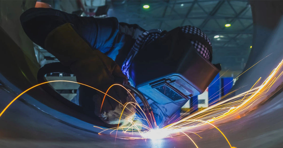
As welders, it’s important to realize that we’ll be MIG welding thin metals, thick metals, and everything in between. We cope with such projects by adjusting our technique and equipment settings to account for project gauge variations. Case in point, whether a DIY enthusiast or a hobbyist, we’ve all heard of burn-through, which is when a metal part experiences localized melting. A hole literally burns through a part when excessive arc heat is applied. Similarly, when working on thicker workpieces, poor penetration can occur if process parameters are geared towards thinner work.

Source: https://weldrun.com/burn-through-welding/
Situations like these are commonly brought about by incorrect equipment settings. They’re fixable with a little welding know-how. If it seems like a hole might burn through a thin sheet, equipment heat input levels can be reduced. Conversely, if a weak joint forms because the weld pool won’t penetrate deep enough into a thick piece of metal, more arc energy is needed. Thin or thick, the width of the base metal part is accounted for by equipment settings. In order to master those settings, plus the techniques required to take advantage of them, we need to know more differently gauged metal thicknesses.
Beginning with the relationship between weld thickness and weld parameters, we’ll create a guide to help us achieve better results, welds that never burn-through and never lack penetration strength. It begins with definitions and a way to interpret metal thickness/thinness (gauge) that is purely objective and based on quantifiable data.
Understanding The Connection Between Metal Thickness and Weld Technique
Before diving into the equipment settings, wire feed specs, and shielding gas blends that’ll impact how a welding arc impacts thick or thin metals, this is an opportune moment to talk about those thicknesses and the techniques required to successfully pull off a strong, distortion-free weld. Sheet metal sections that are 0.6mm to 3mm thick are the logical place to begin. From HVAC ducting to automotive panels, such semi-rigid sheets are an integral part of countless commercial and industrial applications.

Unable to absorb and distribute large amounts of arc heat, welders use bead weaving techniques. This is when intermittently applied stitch welds are laid down in a weave pattern. Small tack welds also help, backed by a heatsink of some kind. The goal is to manage heat distribution, to lower the chances of thin metal distortion at all costs.

Source: https://beginnerweldingguide.com/mig-welding-patterns-for-beginners/
Generally speaking, 3mm to 6mm thick metals are considered moderately thin, lightweight, flexible, and durable. They’re fully rigid and utilized in some construction applications and for heavier vehicle components, such as car crumple zones. They’re easy to form and fabricate due to a flexible, ductile mechanical structure. Thick metals, on the other hand, those that are over 12mm thick, are typically used for structural purposes where strength and durability are paramount. These metals are commonly found in construction and heavy machinery.

Source: https://carsafetyfeature.weebly.com/crumple-zone.html
Medium to thick metal workpieces are imbued with superior heat distribution. Burnthrough problems are now unlikely, but there’s a new defect to be aware of during the MIG welding process. We’re, of course, referring to penetration strength. The weld puddle must fluidize efficiently so that a deep fusion joint is created. Prep work is called for now. A preheat phase accompanied by joint cleaning might be in order. As for the welding technique employed, single and multi-pass techniques are applicable to both medium and thicker metals. It’s a challenge getting the bead to flow deep, so other techniques may come into play, including machine-cut bevels and/or grooves. A bigger diameter of filler wire and a shielding gas that facilitates deeper fluid bead penetration may also be required.

Source: https://amarineblog.com/2017/09/15/welding-inspector-wps-part-8-final/
Evaluating The Contribution of Welder Skill Levels
Manually entered heat input settings can be entered by expert welders when working on different metal thicknesses. Novices can count on Synergic Controls on their Tooliom machines to help sidestep this particular hurdle. All the same, the possibility of messing up a job because the metal is too thick or too thin just complicates matters. Different types of weld joints, welding positions, geometrically complex parts, all of these factors introduce challenges. Since this is an article about welding different thickness metals, it’s important to note that welding thicker metals presents its own set of challenges. Welders must consider factors such as preheating, proper filler wire selection, deep penetrating shielding gasses, and the use of specialized techniques that’ll ensure a strong and reliable weld.
Welding thicker metals requires a higher level of skill and expertise, as any mistakes or improper techniques can lead to structural integrity issues. That’s not to say that the welding of thin sheet metals is easy. It’s not easy at all, not when the arc heat generated by a powerful MIG welding rig generates enough heat to burn a hole all the way through the sheet. At the very least, distortion problems could ruin the work and the welder’s reputation in one awful rush of adrenaline.

At worst, as part of a prestigious welding team, a hard-to-replace component is ruined. Even in a smaller garage, disasters await a welder who’s set his arc incorrectly. A thin sheet section on a client’s prized car ends up permanently ruined, and the job is lost in one reckless instant. With these thoughts firmly in mind, it really is crucial for welders to continuously expand their knowledge and skills so that they know the ins and outs of working with different metal thicknesses.
Metal Thickness and Equipment Parameters Relationships Explained
There’s going to be a table at the end of this post. Pride of place on that data table, equipment voltage, and amperage occupy two columns. To see those controls in action, look for them on a Tooliom TL-200M MIG welding machine. Located right below the digital display, voltage on the left, and current on the right, the two knobs provide an initial stopping spot for entering our thickness settings in the MIG process.

MIG/Stick/TIG Multi-Process Welder TL-200M 3 in 1 Welding Machine|Tooliom
Beginners often get their settings wrong. That’s all right. With a little practice, mistakes are made and learned. Hopefully, with no damage done, novices soon zero in on optimal settings on configurations that are correctly set within that thickness sweet spot we all seek. There’s no burn-through overheating in that sweet spot, and neither is there any heat attenuated arc weakness where a poorly penetrating weld joint can form. That ideal welding arc isn’t guessed at, nor is it found by luck. The thickness of the base metal is noted by the welder as soon as he takes on the project. That way, both knobs can be adjusted to generate the correct quantity of arc energy.

Looking back at the Tooliom TL-200M, the term “Synergic Control” gets a lot of attention. This feature allows for automatic adjustment of the weld parameters based on the metal gauge. It eliminates the need for manual adjustments and ensures consistent and optimal welds. Additionally, the TL-200M has a wide range of amperage settings, making it suitable for welding various metal thicknesses. With this machine, beginners can easily learn and master MIG welding techniques for different metal thicknesses. However, pro welders should know how to MIG weld different metal thicknesses. While an excellent feature, Synergic Control, seasoned veteran welders should know how to set these controls in the welding “goldilocks” zone by themselves.

By upping the voltage, wider, deeper weld beads are formed. Greater heat input is possible with higher voltages, making the setting ideal for thicker workpieces. Conversely, to avoid burn-through, the equipment settings should be configured with a lower voltage. As for amperage (electrical current), Higher currents are favored when a welder is configuring their equipment for thicker applications.
Those are simple enough conventions for welders to remember. For thin workpiece welding, lower the current and voltage. Switching over to a thicker piece of metal, a project that’ll need deeper penetration, welders will obviously opt for higher voltages and currents. It’s just about that simple. But here’s another “however” to cause trouble. These settings, at least for the moment, seem rather vague. Of course, a scrap piece of metal can be worked on, a piece that’s of a similar thickness as the project piece. On that scrap piece, the welder fine tunes amperage and voltage until the bead is moving at the correct travel speed and the weld puddle is fluidized as desired.

The setting of current and voltage, travel speed, wire feeding speed(WFS) on the influence of weld.
Source: https://ewi.org/gas-metal-arc-welding-basics-travel-speed-and-contact-to-work-distance-ctwd/
Again, the solution might be to turn to the Synergic Control on the Tooliom TL-200M, but what if this exceptional welding machine isn’t available? True, most modern MIG welding equipment integrates some type of auto-settings, and they quickly adjust to compensate for the voltage and travel speed according to a particular metal type or thickness, but welders should still be trained so that they at least have a passing familiarity with their gear’s manual controls. The most obvious option is to seek out a welding chart, a data table. Based on metal thickness, often recorded in millimeters, such tables include important welding parameters, like travel speed and wire diameter. Electrode diameter and shielding gas flow rate are two other parameters found on such charts.

Factors for Intelligently Configuring Every Equipment Parameter
By all means, the two knobs should be adjusted higher for thicker applications and lower for thin sheet metal components. Charts are consulted, test workpieces are welded, and welding techniques are refined. There’s still more to do. For one thing, the diameter of the wire feeding into the weld pool should match the application, too. Again, look at a data table or chart for this information. Is the metal mild steel or stainless? Is it an aluminum alloy with a low melting point or a duplex steel with an elevated melting point? This information must be known if the base metal and wire are to fuse predictably as the weld bead travels.
Then there’s the shielding gas provided in the cylinder. Is it pure argon? Good for non-ferrous alloys, argon doesn’t always provide the deepest penetration. Back with the thinner sheet metal example, arc stability becomes a problem when certain gasses are employed. If the arc isn’t stable, it won’t push or pull the weld bead efficiently. More thermal energy is then required to get the required effect, at which point the issue of burn-through comes back to haunt the welder. To keep weld parameters tuned to the desired input heat, the appropriate shielding gas must be matched to the pre-configured equipment amperage/voltage settings, which, in turn, dictates the quantity of energy required to produce a strong joint on a metal part that’s of a known gauge.

Closing Thoughts: Seeking Strong Welds Across Different Metal Thicknesses
Curiously, there’s a knock-on effect present in the process. To reach a desired welding thickness, the material type and its melting point are noted. The shielding gas is decided upon based on these notes, then the wire type and diameter, then the voltage/amperage parameters and the wire travel speed, too. Done correctly, all of these parameters and accompanying facts about the situation combine equitably to create a strong joint that penetrates just deep enough while eliminating the possibility of any burn-through. Even the merest hint of workpiece deformation is neutralized when this approach is utilized.
Still, it’s not easy to weigh all of these factors, which is why common wire types and diameters, Synergic Controls, and numerous metal thickness charts should be made available whenever possible. Tied to the equipment settings, there’s the shielding gas selected and the diameter/composition of the filler wire. The rest, technique especially, is up to the on-site welder.

This means that none of these carefully input settings and wire/cylinder fittings will do any good unless the professional in charge of the application uses a thickness-corresponding welding technique. Unable to distribute arc heat, thin metals benefit from the previously covered stitch technique and intermittently applied weld joints. Going above 3mm and beyond, the welder calls upon conventional multi-pass techniques and all of the methods available that will realize a deep, penetrating, strong fusion joint that lasts.
|
Thin Metals |
Medium Metals |
Thick Metals |
|
|
Metal Thickness |
0.6mm to 3mm |
3mm to 12mm |
Greater than 12mm |
|
Heat Input |
Low arc output |
Moderate arc |
High arc heat |
|
Wire Type |
Thin electrode and thin diameter filler |
Medium diameter wire |
Largest diameter wire feed |
|
Shielding Gas |
Argon, Argon-O2, Ar-He-O2 |
Argon-CO2 mix |
Argon-CO2 |
|
Applications |
Sheet metal fabrication |
Light structural applications |
Load-bearing supports, heavy vehicles, construction |
Note: Different metals require different shielding gasses. Consult welding charts for more details. Additionally, while CO2 does encourage deeper penetration, its use promotes more splatter.

How to MIG Weld Different Thickness Metals - FAQ
Q: 1. What is burn-through in MIG welding, and how can it be prevented in thin metal welding?
A: Burn-through is when a hole is burned through a metal part due to excessive arc heat during welding. To prevent burn-through in thin metal welding, welders can reduce equipment heat input levels and use bead weaving techniques with intermittently applied stitch welds to manage heat distribution.
Q: 2. How does weld thickness affect welding techniques and equipment settings?
A: Thicker metals may require higher voltages and currents to achieve deep penetration, while thinner metals may need lower heat input levels to avoid burn-through.
Q: 3. How does Synergic Control on the Tooliom TL-200M MIG welding machine assist with welding different metal thicknesses?
A: Synergic Control on the Tooliom TL-200M MIG welding machine automatically adjusts the weld parameters based on the metal gauge, eliminating the need for manual adjustments and ensuring consistent and optimal welds.